巧设Toggle Rate避开规则检查
0赞在特权同学的《Cyclone III原型开发调试》一问中,提到的第一个遇到的问题就是EP3C5E144/EP3C10E144/ EP3C16E144/ EP3C25E144器件在PIN12分配给EPCS控制器的DCLK信号时,PIIN11无法使用。
问题的产生是这样的,当在一个NIOS2系统中添加了一个EPCS控制器外设后,Cyclone III和之前的器件不一样,需要设计者手动分配各个管脚。在《Quartus II Handbook, Volume 5: Embedded Peripherals.pdf》的EPCS Device Controller Core一节中,把作为手动分配的Cyclone III需要做的注意事项提得很清楚。如图1所示,PIN12管脚分配给了EPCS控制器的时钟DCLK,而PIN11分配给了SDRAM的D0。在这个设 计者中,特权同学很认真仔细的做了管脚分配,然后编译,得到的回报却是如下所示的error信息:
Error: Cannot place I/O pin sdram_data[0] with I/O standard 3.3-V LVTTL in pin location 11 -- possible switch coupling with I/O pin epcs_dclk in pin location 12.

图1
虽然已经猜到了是工具在编译的时候特别的对器件的相邻管脚间一些电气特性做了特殊的检查,检查的初衷当然是好的,但是问题是也许设计者的设计本身好像不存在这方面的问题,也似乎没有这个检查的必要。
后来,在《AN466:Cyclone III Design Guidelines》中关于Pad Placement Consideration一节有如下描述:
In specific applications, you can relax the restriction checks in the Quartus II software.For instance, if you have a non-toggling single-ended pin, you can place it closer to a differential pin safely, thereby bypassing pin placement checks. To set this in the Quartus II software, assign 0 MHz toggle rate to Toggle Rate assignments for the pin in the Assignment Editor. The Output Enable Group assignment is another setting that is useful especially in external memory interfaces to allow efficient placement of output or bidirectional pins in a VREF group when a voltage referenced input is used in the group.
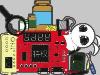
其大意也是说到对于一些挨着差分信号的管脚,如果这个管脚本身并非是频繁变化的信号,那么可以放宽他的检查要求,前提当然是设计者可以确保它能够安全的和 差分信号挨着并且正常工作。至于设置避开对用户来说过于严厉的检查,方法也很简单,在Pin Planner中将相应管脚的Toggle Rate设置为0MHz即可。如图2所示,这里是设置PIN_12的Toggle Rate为0MHz。当然,设置PIN_11为0MHz也是没有问题的。

图2
《Cyclone III原型开发调试》:
http://blog.chinaaet.com/detail/11160.html