ARM DynamlQ架构的power介绍
0赞ARM的处理器,在power架构,根据cluster的架构的变化而发生了变化。
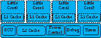
一、big-little的power架构
如下图,是big-little的power 架构,整个cluster的所有组件,均使用相同的电压域。用虚线框包围的区域,表示该模块,有单独的power domain。
二、DynamlQ的power架构
arm在推出DynamlQ架构之后,也推出了新的power架构,不然,无法精细化的控制power。如下图所示:
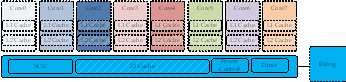
不同的颜色,表示不同的电压域,用虚线框包围的,表示该模块,有单独的power domain。
可以看出,采用DynamlQ架构之后,每个core,有自己的电压域。
相比之前的big-little架构,取消了,很多信号。
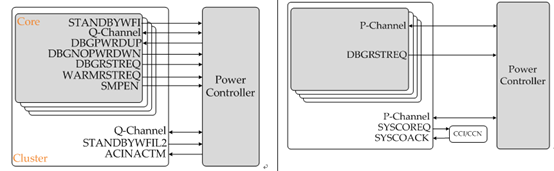
左边,是big-little架构下,core与power controller(以下简称PMU)的信号连接:
信号 | 说明 |
STANDBYWFI | core是否进入wfi状态 |
Q_Channel | Q-channel通道,用于控制core的power |
DBGPWRDUP | debugger的core上电请求 |
DBGNOPWDRDWN | debugger强制片内PMU,不允许对core下电的请求 |
WARMRSTREQ | core的warm reset请求 |
SMPEN | core的snoop使能请求 |
而cluster,与PMU的信号连接如下:
信号 | 说明 |
Q-Channel | Q-Channel通道,用于控制cluster的power |
STANDYWFIL2 | cluster是否处于wfi状态 |
ACINACTM |
右边,是DynamlQ架构下,core与pmu的信号连接:
信号 | 说明 |
P-Channel | P-channel通道,用于控制core的power |
DBGRSTREQ | core的warm reset请求 |
而cluster与pmu的信号连接如下:
信号 | 说明 |
P-Channel | P-channel通道,用于控制cluster的power |
SYSCOREQ | cluster coherency请求 |
SYSCOACK | CCI/CCN总线矩阵的coherency响应 |
关于SYSCOREQ和SYSCOACK的解释如下:

三、P-Channel
P-channel的详细解析,可以看我之前写的博文:http://www.lujun.org.cn/?p=3634
对于P-Channel,有以下的一些信号:
Signal | Description |
PREQ | Power transition request. |
PSTATE | Power transition state. PSTATE[3:0] is for power mode, and PSTATE[7:4] is for operating mode. |
PACTIVE | The minimum power transition state requirement. The highest set HIGH bit indicates the required minimum power requirement separately for power mode and operating mode. This can be hint for power controller. PACTIVE[15:0] is for power mode, and PACTIVE[31:16] is for operating mode. |
PACCEPT | Power transition request is accepted. |
PDENY | Power transition request is denied. |
PMU就是通过P-Channel,来和core以及cluster来通信,实现power的控制。
四、power mode
power mode,表示硬件power的状态,分为core的power mode和cluster的power mode。
1、core的power mode
power mode有以下一些模式:
Power Mode | Description |
ON | In this mode, the core is fully functional. |
FUNC_RET | This is a retention mode for the Ad-SIMD/FP unit. It can be entered when there are no instructions in the pipeline or pending for this unit. This mode can be enabled or disabled by software. A timeout value for entry into this mode from the last SIMD/FP instruction execution can be programmed. |
FULL_RET | This is a retention mode for the full core domain. It can be entered when the core is in WFI/WFE. This mode can be enabled or disabled, separately for WFE and WFI. Separate timeout values for entry into this mode from WFE and WFI entry can be programmed. Direct transitions between ON and FULL_RET are only allowed when:
|
OFF_EMU | This mode allows functional emulation of power off, whilst still maintaining debug state and allowing debug access. |
OFF | This mode allows the core to be powered off. This mode powers off the complete core power domain. Hardware flushing of the L1 and L2 caches when OFF or OFF_EMU should be added. |
DBG_RECOV | This mode allows cache memory contents and RAS registers to be preserved over a reset for debug purposes. This mode can be used to assist debug of external watchdog-trigger reset events when the whole system hangs. In this application, cluster power on reset or warm reset should be used together. |
可见,在DynamiQ架构下的power,core的power模式,有多种模式。定义这么多模式,也是为了能够精细化的控制。
PSTATE and PACTIVE 编码如下:
Power Mode | PSTATE[3:0] | PACTIVE[15:0] Related bit |
ON | 4'b1000 | 8 |
FUNC_RET | 4'b0111 | 7 |
FULL_RET | 4'b0101 | 5 |
OFF_EMU | 4'b0001 | 1 |
OFF | 4'b0000 | 0 (always tied to 1'b0) |
DBG_RECOV | 4'b1010 | - |
比如,core要进入OFF状态,那么core会驱动P-Channel上的PACTIVE信号的0bit为1,PMU发现该bit为1,表示core要进入OFF状态。于是驱动PSTATE为4'b0000,并设置PREQ为1,发起power mode切换请求。core接收到该请求后,如果允许外部的PMU对core下电,会将PACCEPT信号拉高,PMU检测到该信号为高后,就可以将core断电了。
如果core不允许外部的PMU对core下电,会将PDENY信号拉高,PMU检测到该信号为高后,就知道不能对core断电。
2、cluster的power mode
cluster的power mode有如下4种:
Power Mode | Description |
ON | In this mode, the cluster is fully functional. |
FUNC_RET | This is a retention mode for the L3 Cache RAM whilst the cluster is still functional. This mode can be enabled and disabled by software running on any of the cluster cores. A timeout value for entry into this mode from the last L3 cache access can be programmed. |
MEM_RET | This mode allows the cluster logic to be off whilst retaining the L3 Cache RAM. This mode can be entered when the cluster is idle and all cores are OFF. |
OFF | This mode allows the cluster to be powered off. This mode powers off the full cluster domain. Hardware flushing of the L3 Cache should be added when OFF is requested on the cluster P-Channel. |
PSTATE和PACTIVE编码:
Power Mode | PSTATE[3:0] | PACTIVE[15:0] Related bit |
ON | 4'b1000 | 8 |
FUNC_RET | 4'b0111 | 7 |
MEM_RET | 4'b0010 | 2 |
OFF | 4'b0000 | 0 (always tied to 1'b0) |
DBG_RECOV | 4'b1010 | - |
比如,cluster要进入OFF状态,那么core会驱动P-Channel上的PACTIVE信号的0bit为1,PMU发现该bit为1,表示cluster要进入OFF状态。于是驱动PSTATE为4'b0000,并设置PREQ为1,发起power mode切换请求。cluster接收到该请求后,如果允许外部的PMU对core下电,会将PACCEPT信号拉高,PMU检测到该信号为高后,就可以将cluster断电了。
如果cluster不允许外部的PMU对cluster下电,会将PDENY信号拉高,PMU检测到该信号为高后,就知道不能对cluster断电。
五、寄存器
为了支持DnyamlQ架构的power精细化控制,arm定义了一些系统寄存器,用来软件控制硬件的power mode。
寄存器分为,对core和cluster。
1、对core
CPUWRCTLR_EL1和 DBGPRCR_EL1,两个系统寄存器。
Registers | Bit | Name | Description |
CPUPWRCTLR_EL1 | [0] | PWRDN_EN | Power off enable bit. This is used by software when the core is ready to be inactive at the next entry to WFI. The SMPEN bit from previous generation processors is removed. |
[3:0] | RESERVED | ||
[6:4] | WFI_RET_CTRL | System counter tick control. When in multi-thread processor, larger one will be selected for whole core retention control. | |
[9:7] | WFE_RET_CTRL | System counter tick control. When in multi-thread processor, larger one will be selected for whole core retention control. | |
[12:10] | SIMD_RET_CTRL | System counter tick control. When in multi-thread processor, larger one will be selected for whole core retention control. | |
[31:13] | RESERVED | ||
DBGPRCR_EL1 | [0] | CORENPDRQ | Request emulate power down if the system will power down the core. In multi-thread processor, if one thread has set this bit, the "no power down" request will be active. |
软件如果写bit0为1,表示要将core下电。当后续的程序执行wfi指令之后,core就会通过P-Channel的pactive,向PMU,发送off请求。
2、对cluster
cluster有以下寄存器:
- cluster-down寄存器,控制power off和memory retention
- power 控制寄存器:控制function retention,L3 cache RAM size
- performance monitor:控制cache部分power off
Registers | Bit | Name | Description |
CLUSTERPWRDN_EL1 (banked per-thread per- core) | [0] | Cluster power required | Cluster power down request. If a thread sets its bit to 1'b1, it request that the cluster remains ON when all cores are off. If a thread sets to 1'b0, it requests that the cluster goes to OFF when all cores are off. If any of the banked cluster power requests is set to 1'b1, the cluster will remain ON when all cores are off. If all of the banked cluster power requests are set to 1'b0, the cluster will go to OFF when all cores are off. |
[1] | Memory retention required | Memory retention enable bit. If a thread sets its bit to 1'b1, it request that the cluster goes to MEM_RET when all cores are off. If a thread sets to 1'b0, it requests that the cluster goes to OFF when all cores are off. If any of the banked cluster power requests is set to 1'b1, the cluster will go to MEM_RET when all cores are off. If all of the banked cluster power requests are set to 1'b0, the cluster will go to OFF when all cores are off. | |
[31:2] | RAZ | ||
CLUSTERPWRCTLR_EL1 | [2:0] | L3 Cache Ram Retention Control | System counter tick control. |
[3] | RAZ | ||
[7:4] | Cache Portion Power Request | These bits are output on CLUSTERPACTIVE[19:16] to indicate to the power controller which cache portions must be powered. | |
[31:8] | RAZ | ||
CLUSTERL3HIT_EL1 | [31:0] | L3 Cache hit count | Count of number of L3 Cache hit. |
CLUSTERL3MISS_EL1 | [31:0] | L3 Cache miss count | Count of number of L3 Cache misses. |
六、cache的power
DynamlQ架构的cache的power mode,是多种组合。如下图:
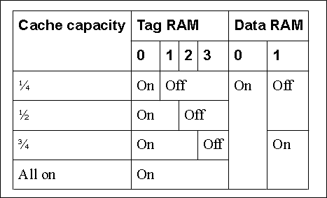
就是看tag ram和data ram的上电状态。至于为什么cache,会有这么多种power mode,是因为DynamlQ架构下,cache变大很大。L2 cache成每个core私有的,并且还增加了L3 cache。如果不对cache的power,做精细化的管理,那么功耗,也就上去了。
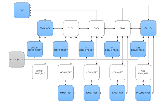
下图是power mode的转换图:
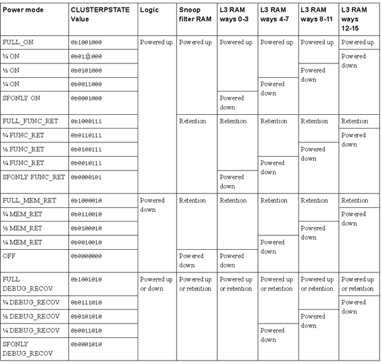
以下是power mode的编码:
七、总结
为了适应复杂的DynamIQ架构,arm将power的架构也做了很大的修改。其中一点,是引入了P-Channel,实现更负责的power状态控制。以及对硬件,定义了很多的power mode,用于软件来方便的控制,从而实现低功耗。