从0开始学Zedboard(3)GPIO控制OLED
0赞
发表于 2015/1/5 下午8:49:01
阅读(9126)
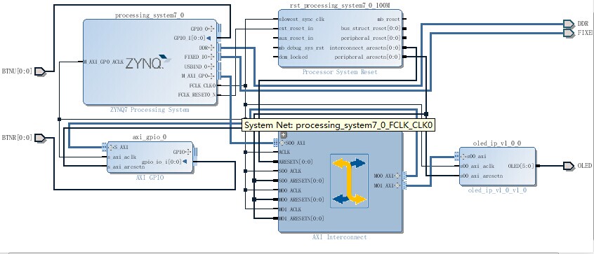
今天,我们要利用PS_GPIO、AXI_GPIO、EMIO分别控制OLED来显示不同的页面。首先是建立VIVADO工程。OLEDIP核建立参考http://xilinx.eetrend.com/blog/7899,里面有详尽的说明。按照下图建立工程。
我们这次实验,利用AXI_GPIO连接BTNR,PS通过EMIO连接BTNU,通过PS GPIO连接BTN8、BTN9,对三种方式的GPIO均进行了控制演示。
XDC约束文件为:
#####################OLED##################

# DC

 set_property PACKAGE_PIN U10 [get_ports {OLED[0]}]

 set_property IOSTANDARD LVCMOS33 [get_ports {OLED[0]}]

 # RES

 set_property PACKAGE_PIN U9 [get_ports {OLED[1]}]

 set_property IOSTANDARD LVCMOS33 [get_ports {OLED[1]}]

 # SCLK

 set_property PACKAGE_PIN AB12 [get_ports {OLED[2]}]

 set_property IOSTANDARD LVCMOS33 [get_ports {OLED[2]}]

 # SDIN

 set_property PACKAGE_PIN AA12 [get_ports {OLED[3]}]

 set_property IOSTANDARD LVCMOS33 [get_ports {OLED[3]}]

 # "BAT"

 set_property PACKAGE_PIN U11 [get_ports {OLED[4]}]

 set_property IOSTANDARD LVCMOS33 [get_ports {OLED[4]}]

 # "VDD"

 set_property IOSTANDARD LVCMOS33 [get_ports {OLED[5]}]

 set_property PACKAGE_PIN U12 [get_ports {OLED[5]}]

#######################AXI_GPIO#####################

 set_property IOSTANDARD LVCMOS25 [get_ports BTNR]

 set_property PACKAGE_PIN T18 [get_ports BTNU]

#######################EMIO#######################

 set_property IOSTANDARD LVCMOS25 [get_ports BTNU]

 set_property PACKAGE_PIN R18 [get_ports BTNR]

#######################XDC END######################
产生bitstream后,打开SDK,新建立helloworld工程,将helloworld.c改为如下代码:
#include <stdio.h>

#include "platform.h"

#include "xil_types.h"


#include "xgpio.h"

#include "xparameters.h"

#include "xgpiops.h"

#include "xil_io.h"

#include "oled.h"


//extern char inbyte(void);//调用inbyte接收一个字节输入函数

extern XGpioPs_Config XGpioPs_ConfigTable[XPAR_XGPIOPS_NUM_INSTANCES];

int main()

{

  static XGpioPs psGpioInstancePtr;

  XGpioPs_Config*GpioConfigPtr;

  static XGpio GPIOInstance_Ptr;


  int xStatus,start,end;

  u32 Readstatus1,Readstatus2;

  int iPinNumberld9 = 7;  /*Ld9 is connected to MIO pin 7*/

  int iPinNumberbtn8 = 50;/*Btn8 is connected to MIO pin 50*/

  int iPinNumberbtn9 = 51;/*Btn9 is connected to MIO pin 51*/

  int iPinNumberBTNU = 54;/*BTNU is connected to EMIO pin 54*/

  init_platform();

  print("##### Application Starts #####\n\r");

  print("\r\n");

  //~~~~~~~~~~~~~~~~~~~~~~~~~~~~~~~~~~~~~~~~~~~~~~~~~~~~~~~~~~~~~~~~~~~~~~~~~~~

  //Step-1 :AXI GPIO Initialization

  //~~~~~~~~~~~~~~~~~~~~~~~~~~~~~~~~~~~~~~~~~~~~~~~~~~~~~~~~~~~~~~~~~~~~~~~~~~~

  xStatus = XGpio_Initialize(&GPIOInstance_Ptr,XPAR_AXI_GPIO_0_DEVICE_ID);

  if(XST_SUCCESS != xStatus)

    print("GPIO INIT FAILED\n\r");

  //~~~~~~~~~~~~~~~~~~~~~~~~~~~~~~~~~~~~~~~~~~~~~~~~~~~~~~~~~~~~~~~~~~~~~~~~~~~

  //Step-2 :AXI GPIO Set the Direction

  //~~~~~~~~~~~~~~~~~~~~~~~~~~~~~~~~~~~~~~~~~~~~~~~~~~~~~~~~~~~~~~~~~~~~~~~~~~~

  XGpio_SetDataDirection(&GPIOInstance_Ptr, 1, 1);//input

  //~~~~~~~~~~~~~~~~~~~~~~~~~~~~~~~~~~~~~~~~~~~~~~~~~~~~~~~~~~~~~~~~~~~~~~~~~~~

  //Step-3 :PS GPIO Intialization

  //~~~~~~~~~~~~~~~~~~~~~~~~~~~~~~~~~~~~~~~~~~~~~~~~~~~~~~~~~~~~~~~~~~~~~~~~~~~

  GpioConfigPtr = XGpioPs_LookupConfig(XPAR_PS7_GPIO_0_DEVICE_ID);

  if(GpioConfigPtr == NULL)

    return XST_FAILURE;

  xStatus = XGpioPs_CfgInitialize(&psGpioInstancePtr,

      GpioConfigPtr,

      GpioConfigPtr->BaseAddr);

  if(XST_SUCCESS != xStatus)

    print(" PS GPIO INIT FAILED \n\r");

  //~~~~~~~~~~~~~~~~~~~~~~~~~~~~~~~~~~~~~~~~~~~~~~~~~~~~~~~~~~~~~~~~~~~~~~~~~~~

  //Step-4 :PS GPIO pin setting to Output

  //~~~~~~~~~~~~~~~~~~~~~~~~~~~~~~~~~~~~~~~~~~~~~~~~~~~~~~~~~~~~~~~~~~~~~~~~~~~

  XGpioPs_SetDirectionPin(&psGpioInstancePtr, iPinNumberld9,1);

  XGpioPs_SetOutputEnablePin(&psGpioInstancePtr, iPinNumberld9,1);

  XGpioPs_SetDirectionPin(&psGpioInstancePtr, iPinNumberbtn8,0);

  XGpioPs_SetOutputEnablePin(&psGpioInstancePtr, iPinNumberbtn8,1);

  XGpioPs_SetDirectionPin(&psGpioInstancePtr, iPinNumberbtn9,0);

  XGpioPs_SetOutputEnablePin(&psGpioInstancePtr, iPinNumberbtn9,1);

  XGpioPs_SetDirectionPin(&psGpioInstancePtr, iPinNumberBTNU,0);

  XGpioPs_SetOutputEnablePin(&psGpioInstancePtr, iPinNumberBTNU,1);

  //~~~~~~~~~~~~~~~~~~~~~~~~~~~~~~~~~~~~~~~~~~~~~~~~~~~~~~~~~~~~~~~~~~~~~~~~~~~

  //Step-5 :OLED Intialization

  //~~~~~~~~~~~~~~~~~~~~~~~~~~~~~~~~~~~~~~~~~~~~~~~~~~~~~~~~~~~~~~~~~~~~~~~~~~~

  OLED_Init();

  //~~~~~~~~~~~~~~~~~~~~~~~~~~~~~~~~~~~~~~~~~~~~~~~~~~~~~~~~~~~~~~~~~~~~~~~~~~~

  //Step-6 :press btn8 to start Demo

  //~~~~~~~~~~~~~~~~~~~~~~~~~~~~~~~~~~~~~~~~~~~~~~~~~~~~~~~~~~~~~~~~~~~~~~~~~~~

  OLED_ShowString(0,0, "BTN8 to start");

  OLED_Refresh_Gram();


  while (1){

start=XGpioPs_ReadPin(&psGpioInstancePtr, iPinNumberbtn8);

if(start){

XGpioPs_WritePin(&psGpioInstancePtr,iPinNumberld9,1);

print("###################### Demo Starts ########################\r\n");

OLED_ShowString(0,0, "DALE I LOVE U");

OLED_ShowString(0,16, "BTNR to go on");

OLED_Refresh_Gram();

break;

     }

end=XGpioPs_ReadPin(&psGpioInstancePtr, iPinNumberbtn9);

if(end){

XGpioPs_WritePin(&psGpioInstancePtr,iPinNumberld9,0);

OLED_Clear();

break;

  }

  }


  while(1){

 Readstatus1 = XGpio_DiscreteRead(&GPIOInstance_Ptr, 1) ;//读BTNR

 if(Readstatus1){

 OLED_ShowString(0,0, "DO U LOVE ME ?");

 OLED_ShowString(0,16, "BTNU to go on");

 OLED_Refresh_Gram();

 break;

 }

  }

  while(1){

 Readstatus2 = XGpioPs_ReadPin(&psGpioInstancePtr, iPinNumberBTNU) ;//读BTNU

   if(Readstatus2){

   OLED_Clear();

   OLED_ShowString(0,0, "HAHA BYE");

   OLED_ShowString(0,16, "BTN9 to end");

   OLED_Refresh_Gram();


   }

   end=XGpioPs_ReadPin(&psGpioInstancePtr, iPinNumberbtn9);

   if(end){

   XGpioPs_WritePin(&psGpioInstancePtr,iPinNumberld9,0);

   OLED_Clear();

   break;

      }


  }

  print("\r\n");

  print("***********\r\n");

  print("BYE \r\n");

  print("***********\r\n");

  cleanup_platform();

  return 0;

}
同时在hellowworld工程下的src文件下插入font.h oled.c oled.h等字体和oled驱动(见附件)。编译通过后,先programmFPGA,然后run,oled出现”BTN8 to start“,按BTN8出现"DALE I LOVE U BTNR to go on”,LD9点亮,按BTNR出现“DO U LOVE ME? BTNU to go on",按BTNU出现“HAHA BYE BNT9 to end”,最后按BTN9结束Demo,OLED熄灭,LD9熄灭。

