【连载7.4.3】Sobel边缘检测算法的HDL实现
1赞FPGA中针对以上矩阵进行算法移植。由于直接计算会因为负值而得到错误的结果,用补码表示比较繁琐,需要用到unsigned 以及signed类型,不适合FPGA的运算。
cnblog有真oo无双的代码,通过并形乘法、并行相加、平方根来使用,采用各种IP相当的复杂,虽然实现了补码、负数,但看得我都蒙了。为何要把简单的问题复杂化:
http://www.cnblogs.com/oomusou/archive/2008/08/25/verilog_sobel_edge_detector.html
为此Bingo发愤图强(不过oo的博文真的有很好的参考性)!!!!
前面Sobel算子的实现,为了实现FPGA的加速运算,发挥并行流水线的特性,可以划分为4个步骤,解析与实现分别如下:
计算计算Gx与Gy与模板每行的乘积
求得3*3模板运算后的Gx、Gy
为了便于阅读理解,这里(1)与(2),Bingo在同一个always中描述了,但实际上耗费了2个时钟。Gx(Gx_data)与Gy(Gy_data)的计算分别如下:
//-------------------------------------------
//Sobel Parameter
// Gx Gy Pixel
// [ -1 0 +1 ] [ +1 +2 +1 ] [ P11 P12 P13 ]
// [ -2 0 +2 ] [ 0 0 0 ] [ P21 P22 P23 ]
// [ -1 0 +1 ] [ -1 -2 -1 ] [ P31 P32 P33 ]
//Caculate horizontal Grade with |abs|
//Step 1.1
reg [9:0] Gx_temp1; //postive result
reg [9:0] Gx_temp2; //negetive result
reg [9:0] Gx_data; //Horizontal grade data
always@(posedge clk or negedge rst_n)
begin
if(!rst_n)
begin
Gx_temp1 <= 0;
Gx_temp2 <= 0;
Gx_data <= 0;
end
else
begin
Gx_temp1 <= matrix_p13 + (matrix_p23 << 1) + matrix_p33; //postive result
Gx_temp2 <= matrix_p11 + (matrix_p21 << 1) + matrix_p31; //negetive result
Gx_data <= (Gx_temp1 >= Gx_temp2) ? Gx_temp1 - Gx_temp2 : Gx_temp2 - Gx_temp1;
end
end
//---------------------------------------
//Caculate vertical Grade with |abs|
//Step 1.2
reg [9:0] Gy_temp1; //postive result
reg [9:0] Gy_temp2; //negetive result
reg [9:0] Gy_data; //Vertical grade data
always@(posedge clk or negedge rst_n)
begin
if(!rst_n)
begin
Gy_temp1 <= 0;
Gy_temp2 <= 0;
Gy_data <= 0;
end
else
begin
Gy_temp1 <= matrix_p11 + (matrix_p12 << 1) + matrix_p13; //postive result
Gy_temp2 <= matrix_p31 + (matrix_p32 << 1) + matrix_p33; //negetive result
Gy_data <= (Gy_temp1 >= Gy_temp2) ? Gy_temp1 - Gy_temp2 : Gy_temp2 - Gy_temp1;
end
end
具体的实现方式请自行分析代码,Bingo认为这是极简单的……
(3)求得Gx^2+Gy^2的结果,及Gx与Gy的平方和
这一步直接通过HDL中乘法器的描述来实现,综合时会自动布线为片内乘法器,如下:
//---------------------------------------
//Caculate the square of distance = (Gx^2 + Gy^2)
//Step 3
reg [20:0] Gxy_square;
always@(posedge clk or negedge rst_n)
begin
if(!rst_n)
Gxy_square <= 0;
else
Gxy_square <= Gx_data * Gx_data + Gy_data * Gy_data;
end
(4)求得Gx^2+Gy^2的平方根
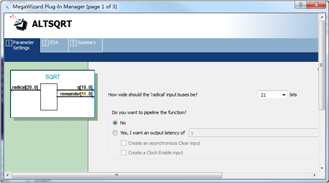
当年Bingo在第一次遇到这个的时候差点崩溃,不过有幸看过无双oo的博文,才知道强大的Altera竟然在LPM中提供了平方根的IP,如下所示:

ALTSQRT的使用非常简单,坦白的说Bingo从来没看到DT。以下直接给出SQRT的例化,从而得到平方根,如下:
//---------------------------------------
//Caculate the distance of P5 = (Gx^2 + Gy^2)^0.5
//Step 4
wire [10:0] Dim;
SQRT u_SQRT
(
.radical (Gxy_square),
.q (Dim),
.remainder ()
);
(5)根据外部输入阀值,判断并实现边缘的检测
简单的判断Dim的大小而已,大于阀值,视为有效,赋1;反之则赋0。这里的Sobel_Threshold由外部输入,暂且认为是60吧。。。
//---------------------------------------
//Compare and get the Sobel_data
//Step 5
reg post_img_Bit_r;
always@(posedge clk or negedge rst_n)
begin
if(!rst_n)
post_img_Bit_r <= 1'b0; //Default None
else if(Dim >= Sobel_Threshold)
post_img_Bit_r <= 1'b1; //Edge Flag
else
post_img_Bit_r <= 1'b0; //Not Edge
end
前面从(1)-(5)中,总共消耗了5个时钟,因此最后对行场、像素有效时钟进行5个clock的偏移,如下:
//------------------------------------------
//lag 5 clocks signal sync
reg [4:0] per_frame_vsync_r;
reg [4:0] per_frame_href_r;
always@(posedge clk or negedge rst_n)
begin
if(!rst_n)
begin
per_frame_vsync_r <= 0;
per_frame_href_r <= 0;
end
else
begin
per_frame_vsync_r <= {per_frame_vsync_r[3:0], matrix_frame_vsync};
per_frame_href_r <= {per_frame_href_r[3:0], matrix_frame_href};
end
end
assign post_frame_vsync = per_frame_vsync_r[4];
assign post_frame_href = per_frame_href_r[4];
assign post_img_Bit = post_frame_href ? post_img_Bit_r : 1'b0;
这样,便完成了Sobel边缘检测算法的移植。工程目录sim文件夹下包含了VIP的Modelsim工程,波形仿真如下(新架构没有*_clken):

最后,在Video_Image_Processor中例化VIP_Sobel_Edge_Detector模块,并且在Video_Image_Processor信号列表中修改输出与阀值输入,相关如下:
…
output post_img_Bit, //Processed Image Bit flag outout(1: Value, 0:inValid)
//user interface
input [7:0] Sobel_Threshold //Sobel Threshold for image edge detect
);
//--------------------------------------
//Image edge detector with Sobel.
VIP_Sobel_Edge_Detector
#(
.IMG_HDISP (IMG_HDISP), //640*480
.IMG_VDISP (IMG_VDISP)
)
u_VIP_Sobel_Edge_Detector
(
//global clock
.clk (clk), //cmos video pixel clock
.rst_n (rst_n), //global reset
//Image data prepred to be processd
.per_frame_vsync (per_frame_vsync), //Prepared Image data vsync valid signal
.per_frame_href (per_frame_href), //Prepared Image data href vaild signal
.per_img_Y (per_img_Y), //Prepared Image brightness input
//Image data has been processd
.post_frame_vsync (post_frame_vsync), //Processed Image data vsync valid signal
.post_frame_href (post_frame_href), //Processed Image data href vaild signal
.post_img_Bit (post_img_Bit), //Processed Image Bit flag outout(1: Value, 0:inValid)
//User interface
.Sobel_Threshold (Sobel_Threshold) //Sobel Threshold for image edge detect
);
endmodule
VIP的例化从略。全编译,下载sof文件,如下图所示,为Sobel_Threshold=60下的边缘检测图(VGA 和USB一样哦)。


