Lattice FPGA中的Ripple Mode之——关于加法器实现的讨论
0赞为什么写这篇博文呢?因为鄙人无意中发现了一个有趣的问题,所以和大家分享一下。其实加法器是很简单的东西,大部分人可能并不注意其在FPGA的具体实现方式。一般情况下,对于简单的加法运算(如三个4bits的数相加),大部分人都是在HDL中直接使用了如下的写法:
module top(a,b,c,d,cout,cin);
    input [3:0] a,b,c;
    output [3:0] d;
    input cin;
    output cout;

    assign {cout,d} = {1'b0,a} + {1'b0,b} + {1'b0,c} + cin;
endmodule
经过Synplify Pro综合得到的结果为:

Diamond中的报告为:
Design Summary
   Number of registers:             0 out of  6047 (0%)
      PFU registers:            0 out of  5936 (0%)
      PIO registers:            0 out of   111 (0%)
   Number of SLICEs:               13 out of  2968 (0%)
      SLICEs as Logic/ROM:          13 out of  2968 (0%)
      SLICEs as RAM:            0 out of  2226 (0%)
      SLICEs as Carry:           3 out of  2968 (0%)
   Number of LUT4s:                19 out of  5936 (0%)
      Number used as logic LUTs:            13
      Number used as distributed RAM:         0
      Number used as ripple logic:          6
      Number used as shift registers:         0
可以发现,综合工具很机智地直接调用了调用了加法器的原语(primitive),综合的结果为,花费了19个LUT4,其中13个用于Logic LUTs,6个用于Ripple Logic。
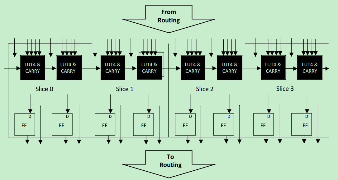
这里需要简单介绍一下Logic LUTs和Ripple Logic的区别,首先看一下PFU的结构图:

Logic LUTs主要用的是上图中的LUT部分的资源,而Ripple Logic则主要用的是上图中的Carry Chain的资源。
所谓Ripple Mode,实际上指的是用于实现一些算术运算的模式,如加法,减法,计数等等。
在Lattice的Datasheet中有这样一句话:

由此,我们可以知道使用进位链(Carry Chain)来实现加法等运算,可以获得更高的性能(更快的速度,更小的Latency),那么是否意味着需要更多的资源呢?莫急,请继续往下看!
首先,我们需要知道,如何让综合工具使用进位链来生成加法器呢?一般来说有两种方法:
方法一:使用约束的方式,在Synplify Pro for Lattice Attribute Reference Manual的文档中,可以找到一个叫做syn_use_carry_chain的Attribute,使用该Attribute,可以实现上述的需求,这里就不详细介绍了,有兴趣地可以自己去尝试一下,该文档可以在Diamond的安装目录中找得到。
方法二:通过IPexpress或者Clarity来生成加法器的IP,默认情况下(位数较低时,当位数高于一定数值时,其会采用LUTs或者DSPs来实现),其将采用Carry Chain来实现加法。具体的过程特别简单,此处不再详述,直接来看看结果:
下图为使用Charity生成的模块框图:

顶层的Verilog代码如下:
module top(a,b,c,d,cout,cin);
    input [3:0] a,b,c;
    output [3:0] d;
    input cin;
    output cout;

    test1 instant1(.adder2_DataA(a),
    .adder2_DataB(b),
    .adder1_DataB(c),
    .adder2_Cin(cin),
    .adder1_Cout(cout),
    .adder1_Result(d));

endmodule
使用Synplify Pro综合的结果图:


扁平视图为:

可以看到,此时生成了CCU2的原语,即Carry Chain。那么Diamond报告中的资源使用情况如何呢?
   Number of registers:             0 out of  6047 (0%)
      PFU registers:            0 out of  5936 (0%)
      PIO registers:            0 out of   111 (0%)
   Number of SLICEs:               8 out of  2968 (0%)
      SLICEs as Logic/ROM:         8 out of  2968 (0%)
      SLICEs as RAM:            0 out of  2226 (0%)
      SLICEs as Carry:           8 out of  2968 (0%)
   Number of LUT4s:                16 out of  5936 (0%)
      Number used as logic LUTs:          0
      Number used as distributed RAM:        0
      Number used as ripple logic:          16
      Number used as shift registers:        0
可以看到,此时只使用了16个LUTs,并且全部都用于了Ripple Logic。
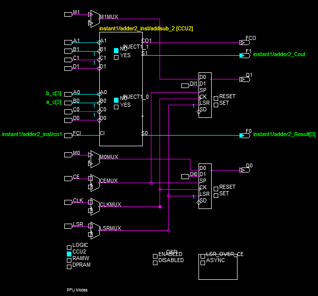
再来看看,具体的实现图,第一个为未使用进位链的某个Slice的图,第二个为使用进位链的某个Slice的图。


图中的左下角,标明了当前PFU的配置模式。
综上所述,既然CCU2模式并未相对于普通模式使用了更多的资源,同时还能获得更高的性能,所以,在使用加法器时,推荐通过IPexpress或者Clarity来配置生成。

