【红色飓风Nano二代测评】编码器串口联调
0赞前几篇测评分别写了LED、串口、旋转编码器,现在我将这些东西连接起来,合成一个整体。首先串口波特率设置模块、串口接收模块这些在以前的博客中已经做了说明了,现在补充一个串口发送模块。
串口发送和接收的模块类似,接收到启动信号之后,将待发数据按照波特率的中间采样点信号将数据通过串口发送引脚发送出去。
串口发送源码如下:
  module my_uart_tx
  (
  	input clk,				//时钟
  	input rst_n,			//复位

  	input	clk_bps,			//波特率信号;高电平为接收或者发送的中间采样点
  	output bps_start,		//启动波特率信号

  	input	rx_int,			//启动发送信号(下降沿启动发送)
  	input[7:0] rx_data,	//待发送信号
  	output rs232_tx		//TXD
  );
  //-------------------------------------------------
  reg[2:0] rxStart;
  wire neg_rx_int;//下降沿标志

  always @ (posedge clk or negedge rst_n)
  begin
  	if(!rst_n)
  		begin
  			rxStart <= 3'd0;
  		end
  	else
  		begin
  			rxStart <= {rxStart[1:0],rx_int};
  		end
  end

  assign neg_rx_int = (rxStart[2:1] == 2'b10);

  //--------------------------------------
  reg[7:0] tx_data;	//等待发送数据的寄存器
  //----------------------------------------
  reg bps_start_r;
  reg tx_en;	//发送使能信 High
  reg[3:0] num;

  always @ (posedge clk or negedge rst_n)
  begin
  	if(!rst_n)
  		begin
  			bps_start_r <= 1'bz;
  			tx_en <= 1'b0;
  			tx_data <= 8'd0;
  		end
  	else if(neg_rx_int)
  		begin
  			bps_start_r <= 1'b1;
  			tx_data <= rx_data;
  			tx_en <= 1'b1;
  		end
  	else if(num==4'd11)
  		begin
  			bps_start_r <= 1'b0;
  			tx_en <= 1'b0;
  		end
  end

  assign bps_start = bps_start_r;

  //-------------------------------------------
  reg rs232_tx_r;

  always @ (posedge clk or negedge rst_n)
  begin
  	if(!rst_n)
  		begin
  			num <= 4'd0;
  			rs232_tx_r <= 1'b1;
  		end
  	else if(tx_en)
  		begin
  			if(clk_bps)
  				begin
  						num <= num + 1'b1;
  						case (num)
  							4'd0:rs232_tx_r <= 1'b0;
  							4'd1:rs232_tx_r <= tx_data[0];
  							4'd2:rs232_tx_r <= tx_data[1];
  							4'd3:rs232_tx_r <= tx_data[2];
  							4'd4:rs232_tx_r <= tx_data[3];
  							4'd5:rs232_tx_r <= tx_data[4];
  							4'd6:rs232_tx_r <= tx_data[5];
  							4'd7:rs232_tx_r <= tx_data[6];
  							4'd8:rs232_tx_r <= tx_data[7];
  							4'd9:rs232_tx_r <= 1'b1;
  							default: rs232_tx_r <= 1'b1;
  						endcase
  				end
  			else if(num==4'd11)
  				begin
  					num <= 4'd0;
  				end
  		end
  end

  assign rs232_tx = rs232_tx_r;

  endmodule
到现在为止,我们这边有串口波特率设置模块、串口发送模块、串口接收模块以及旋转编码器模块。现在就将这些模块连接起来。我们的要求就是通过串口发送数据可以点亮开发板上面的流水灯,同时将旋转编码器采样到的编码器信号通过串口发送到电脑中。
为了便于捕获数据防止数据出错,我们的编码器是一个32位的信号,在这个32位信号的前后各放置一个校验码,即
assign COUNTDat = {8'HAA,COUNT,8'H55};
将所有的子模块全部放置在一个工程中,现在添加一个顶层模块。在这个顶层模块中,我们需要的信号接口有:时钟、复位、AB相信号、八位LED、串口发送和串口接收信号等。则有:
module ENCODER_TOP
(
input clk,
input rst_n,
input inA,
input inB,
output[7:0] led,
input rs232_rx, //receive pin
output rs232_tx //transmit pin
);
然后我们需要一个状态机,在初始状态时我们给发送缓存赋值、然后跳转到下一状态,在这个状态里我们发送一个字节的串口数据(调用串口模块),并等待本次串口数据发送完成。如此循环6次,就发送了6个字节的数据。
顶层的源码如下:
  module ENCODER_TOP
  (
  	input clk,
  	input rst_n,

  	input inA,
  	input inB,
  	output[7:0] led,

  	input rs232_rx,		//receive pin
  	output rs232_tx		//transmit pin
  );
  然后我们需要一个状态机,在初始状态时我们给发送缓存赋值、然后跳转到下一状态,在这个状态里我们发送一个字节的串口数据(调用串口模块),并等待本次串口数据发送完成。如此循环6次,就发送了6个字节的数据。
  顶层的源码如下:
  module ENCODER_TOP
  (
  	input clk,
  	input rst_n,

  	input inA,
  	input inB,
  	output[7:0] led,

  	input	rs232_rx,		//receive pin
  	output rs232_tx		//transmit pin
  );

  wire bps_start1,bps_start2;	//After receiving the data signal, set the baud rate clock start signal.
  wire clk_bps1,clk_bps2;		//
  wire[7:0] rx_data;	//Receive data register, come to save the data until the next
  wire rx_int;		//Remain high during the receive data


  reg[31:0] SendDelay;
  reg ClrTime;
  always @ (posedge clk or negedge rst_n)
  begin
  	if(!rst_n)
  		begin
  			SendDelay <= 32'd0;
  		end
  	else if(ClrTime)
  		begin
  			SendDelay <= 32'd0;
  		end
  	else
  		begin
  			SendDelay <= SendDelay + 1'b1;
  		end
  end


  //------------------------------------
  //------------------------------------

  speed_select	speed_rx( //Baud rate selection module
  						.clk(clk),
  						.rst_n(rst_n),
  						.bps_start(bps_start1),
  						.clk_bps(clk_bps1)
  						);

  my_uart_rx		my_uart_rx(
  							.clk(clk),
  							.rst_n(rst_n),
  							.rs232_rx(rs232_rx),
  							.rx_data(rx_data),
  							.rx_int(rx_int),
  							.clk_bps(clk_bps1),
  							.bps_start(bps_start1)
  						);

  assign led = rx_data;

  reg[7:0] SendDat;
  reg SendFlg;				//发送标志  下降沿 发送一次
  wire[47:0] SendBuf;
  ////////////////////////////////////////////

  speed_select	speed_tx( //Baud rate selection module
  						.clk(clk),
  						.rst_n(rst_n),
  						.bps_start(bps_start2),
  						.clk_bps(clk_bps2)
  						);

  my_uart_tx		my_uart_tx(
  							.clk(clk),
  							.rst_n(rst_n),
  							.rx_data(SendDat),			//准备发送的数据
  							.rx_int(SendFlg),				//给一次下降沿 发一次数据
  							.rs232_tx(rs232_tx),
  							.clk_bps(clk_bps2),
  							.bps_start(bps_start2)
  						);


  ENCODER			ENCODER_inst(
  							.clk(clk),
  							.rst_n(rst_n),

  							.inA(inA),
  							.inB(inB),

  							.COUNTDat(SendBuf)
  						);

  //===========================================

  //收取	rx_int 的下降沿 收到4个了 则说明 接收到了四个数据
  reg[2:0] ccut,TXCCUT;
  always @ (posedge clk or negedge rst_n)
  begin
  	if(!rst_n)
  		begin
  			ccut <= 3'd0;
  			TXCCUT <= 3'd0;
  		end
  	else
  		begin
  			ccut <= {ccut[1:0],rx_int};
  			TXCCUT <= {TXCCUT[1:0],bps_start2};
  		end
  end
  wire RXOver = (ccut[2:1] == 2'b10);	//检测下降沿
  wire TXOver = (TXCCUT[2:1] == 2'b10);	//检测下降沿


  reg[7:0] State;			//状态机
  reg[7:0] RxBuf[3:0];		//接收缓冲区
  reg[3:0] Shift;			//偏移
  reg[7:0] SendDater[5:0];	//
  always @ (posedge clk or negedge rst_n)
  begin
  	if(!rst_n)
  		begin
  			State <= 8'd0;
  			Shift <= 4'd0;
  			SendDat <= 8'd0;
  			SendFlg <= 1'b0;
  			ClrTime <= 1'b0;
  			SendDater[0] <= 8'd0;
  			SendDater[1] <= 8'd0;
  			SendDater[2] <= 8'd0;
  			SendDater[3] <= 8'd0;
  			SendDater[4] <= 8'd0;
  			SendDater[5] <= 8'd0;
  		end
  	else
  		begin
  			case(State)
  				8'd0:
  					begin
  						SendDater[0] <= SendBuf[47:40];
  						SendDater[1] <= SendBuf[39:32];
  						SendDater[2] <= SendBuf[31:24];
  						SendDater[3] <= SendBuf[23:16];
  						SendDater[4] <= SendBuf[15: 8];
  						SendDater[5] <= SendBuf[ 7: 0];
  						ClrTime <= 1'b1;	//计时清零
  						Shift <= 4'd0;
  						State <= State + 1'b1;
  					end
  				8'd1:
  					begin
  						SendFlg <= 1'b1;
  						SendDat <= SendDater[Shift];			//send one
  						State <= State + 1'b1;
  					end
  				8'd2:
  					begin
  						SendFlg <= 1'b0;
  						State <= (TXOver) ? State + 1'b1 : State;	//等待发送完成
  					end
  				8'd3:
  					begin
  						ClrTime <= 1'b0;	//开始计时
  						State <= (SendDelay >= 32'd100000) ? State + 1'b1 : State;	//等待发送完成
  					end
  				8'd4:
  					begin
  						ClrTime <= 1'b1;	//计时清零
  						Shift <= Shift + 1'b1;
  						State <= State + 1'b1;
  					end
  				8'd5:
  					begin
  						State <= (Shift >= 4'd6) ? 8'd0 : 8'd1;
  					end

  				default:begin	State <= 8'd0;end
  			endcase
  		end
  end

  endmodule
如下图1、图2所示在AA与55之间的4个字节即为编码器计数个数。
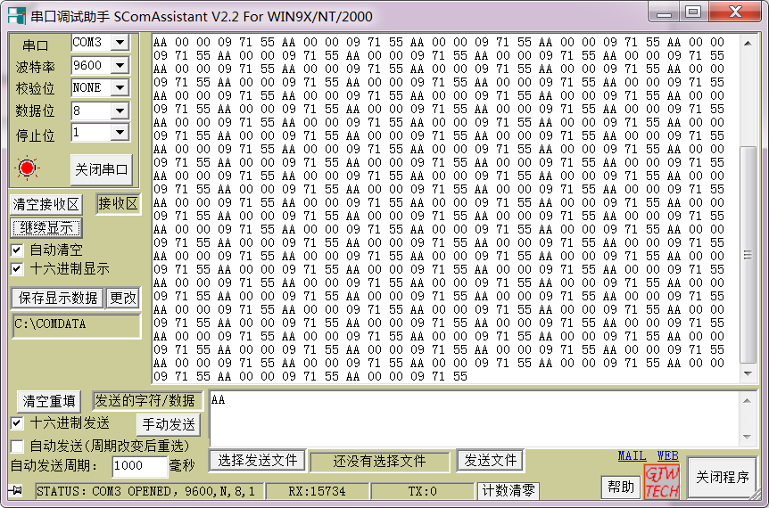
图1 编码器值1
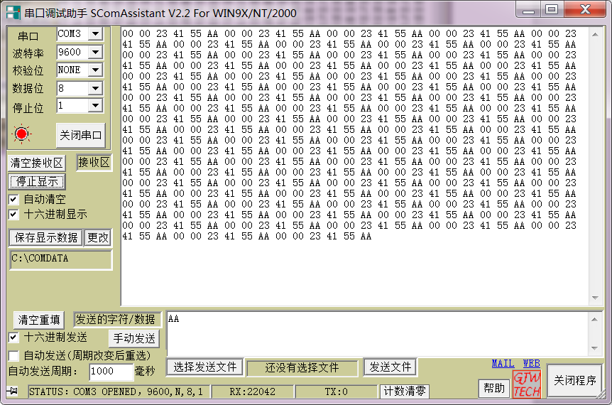
图2 编码器值2
如下图3所示,串口助手发送AA底层显示效果,图4为串口助手发送F0效果。
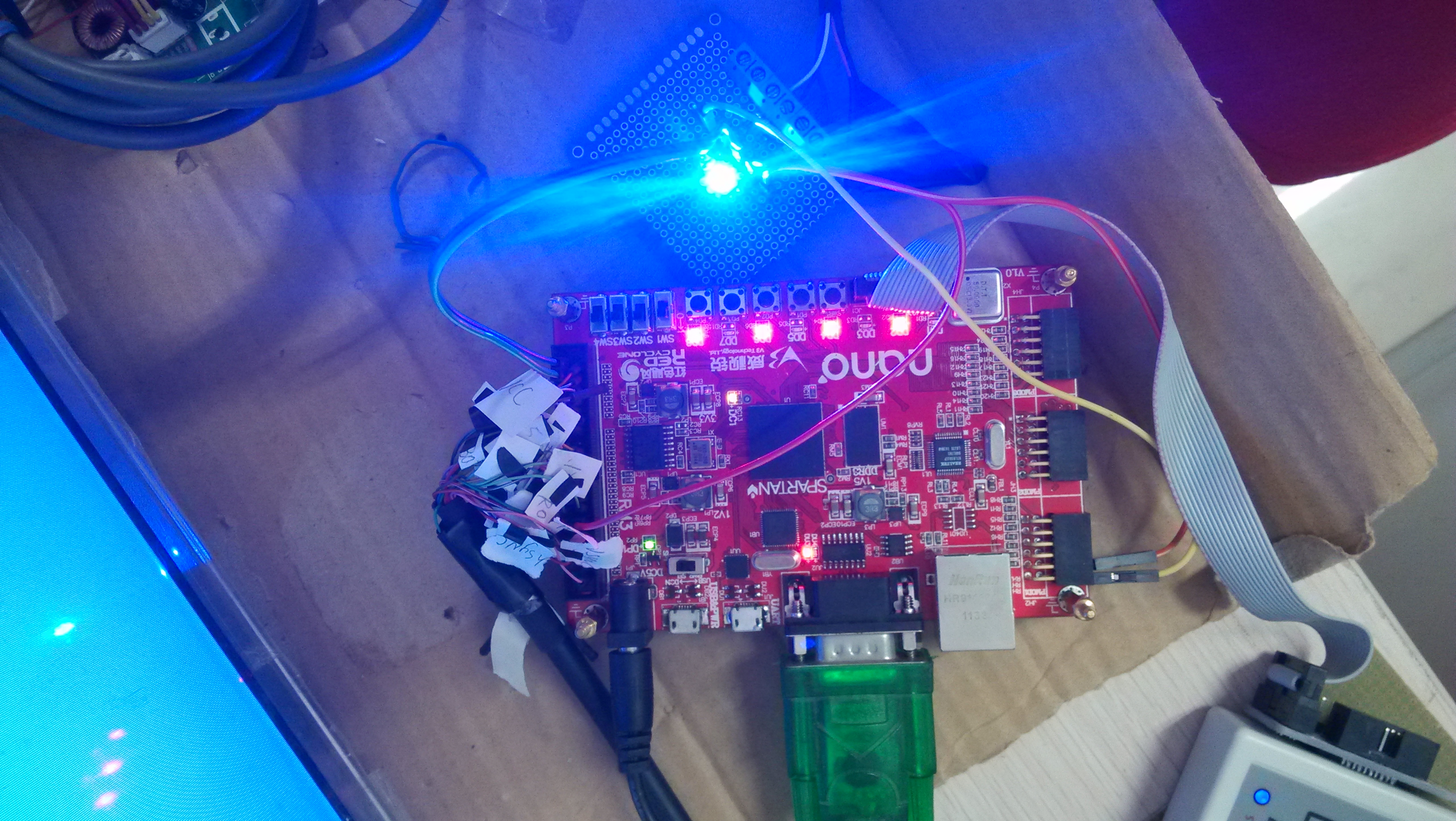
图3 串口发送AA显示效果

图4 串口发送F0显示效果
没有动态的显示感觉始终不是很爽,下一篇,会设计上位机界面,观察下效果。

