FPGA器件预布线,以及ddr3调试问题汇总与总结
1赞最近公司有一个新项目,方案定的是一款Cyclone V Soc FPGA,用到了两个ddr3,一个挂在Qsys系统的HPS里面,一个挂在Logic的Hard Memory Controller那里,这两周一直在跟硬件配合,一起验证器件的管脚配置是否正确。期间在调试这两个ddr3时遇到了好多问题,网上对这方面的资料也比较少,把这些问题的解决方法记录下来。
首先在综合ddr3 ip核时会遇到下面的error
ID:15700 Termination calibration block atom "<name>" uses <name> port, which must be connected to <name>
CAUSE: The specified Termination calibration block atom uses the specified port, but the port is not connected correctly. The port must be connected as specified.
ACTION: Locate the specified port and connect it as specified.
是因为OCT RZQIN这个引脚的问题,因为是用的FPGA逻辑里面的硬核资源做的设计,硬件那边也没有给这个引脚的原理图,找FAE和同事也没有得到很好的解答,在这里搜集资料花了很长时间。
Creating OCT Signals
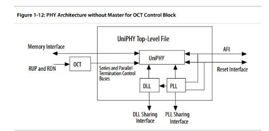
In ALTMEMPHY-based designs, the Quartus Prime Fitter creates the alt_oct block outside the IP core and connects it to the oct_ctl_rs_value and oct_ctl_rt_value signals.
In UniPHY-based designs, the OCT block is part of the IP core, so the design no longer requires these two ports. Instead, the UniPHY-based design requires two additional ports, oct_rup and oct_rdn (for Strati III and Stratix IV devices), or oct_rzqin (for Stratix V devices). You must create these ports in the instantiating entity as input pins and connect to the UniPHY instance. Then route these pins to the top level design and connect to the OCT RUP and RDOWN resistors on the board. For information on OCT control block sharing, refer to “The OCT Sharing Interface” in this volume.
DDR3 datasheet
二、例化步骤
本文皆用DDR3作为实例。例化DDR3 HMC无非有两种方式,直接例化和在Qsys中例化。
7. 生成IP核。顶层文件看似复杂,但是条理非常清楚。
hmc (
input wire pll_ref_clk, //接参考时钟
input wire global_reset_n, //低电平复位
input wire soft_reset_n, //低电平复位,但是不复位PLL
outputwire afi_clk, // 400MHz钟,与内存频率相同,不使用
outputwire afi_half_clk, //没有输出,不使用
outputwire afi_reset_n, //低电平复位
//接下来以mem开头的信号都是接内存芯片的信号,在FPGA上有固定的管脚,这里省略
mem_*// 省略介绍
//接下来以avl开头的信号是AvalonMM 总线,这里省略介绍
avl_*// 省略介绍
//接下来是MPFE的FIFO时钟和复位信号
input wire mp_cmd_clk_0_clk,//接Avalone MM时钟域的钟,可以和afi钟不同
input wire mp_cmd_reset_n_0_reset_n, //接Avalone MM时钟域的复位
input wire mp_rfifo_clk_0_clk, //接Avalone MM时钟域的钟,可以和afi钟不同
input wire mp_rfifo_reset_n_0_reset_n, //接Avalone MM时钟域的复位
input wire mp_wfifo_clk_0_clk, //接Avalone MM时钟域的钟,可以和afi钟不同
input wire mp_wfifo_reset_n_0_reset_n, //接Avalone MM时钟域的复位
//状态信号
outputwire local_init_done, //初始化成功
outputwire local_cal_success, //校准成功
outputwire local_cal_fail, //校准失败
//OCT信号
input wire oct_rzqin //接100欧姆电阻,供校准使用
);
从DDR3的芯片手册和altera关于硬核的使用user guide中我们可以了解到,OCT_RZQIN这个管脚是硬核里面和UniPHY链接做调试校准用的,而且必须放在顶层的module里面 也就是 input OCT_RZQIN而且硬件那里要制定专用引脚,不然全编译后,Quartus会随机给他分配一个引脚。
2、HPS里和硬核里面的管脚都是通过综合后执行pin_assignment.tcl分配好期间的电平标准在全编译后自动分配的专用管脚,如果你手动输入的话,编译会出错,是综合不过去的
3、还有就是你分配的GCLK是不能和ddr3在一个IO Bank里面的 会和硬核里ddr3的专用引脚的电平标准冲突。
以上就是这几天FPGA预布线发现的问题,需要硬件那里做修该的地方。


