stm32F4----驱动12864(八)
1赞
发表于 3/12/2017 12:21:12 AM
阅读(4073)
上一篇中,键盘扫描,还存在几个问题,
(1)等待释放的死循环,这样处理肯定不妥,如果别人按着不放了,其他的事不用做了;
(2)消抖20ms,浪费了时间;
(3)没有实现长按,连击等功能。
后面在改善这几个问题。
今天搞了一天的LCD12864,费了一天。犯了些低级错误,不过在睡觉前搞定了。
关于那些命令和协议就不贴出来了,大把的资料讲这些。
直接上代码吧。
lcd12864.h如下:
#ifndef  _LCD12864_H_
#define  _LCD12864_H_
#ifdef  _cplusplus
   extern "C" {
#endif

#include "stm32f4xx.h"

//*******RS   PB8***********
#define  LCD_RS_PIN    GPIO_Pin_8
#define  LCD_RS_PORT   GPIOB
#define  LCD_RS_CLK    RCC_AHB1Periph_GPIOB

//*******RW   PC6***********
#define  LCD_RW_PIN    GPIO_Pin_6
#define  LCD_RW_PORT   GPIOC
#define  LCD_RW_CLK    RCC_AHB1Periph_GPIOC

//*******EN   PB9***********
#define  LCD_EN_PIN    GPIO_Pin_9
#define  LCD_EN_PORT   GPIOB
#define  LCD_EN_CLK    RCC_AHB1Periph_GPIOB

//*******DB0  PA5***********
#define  LCD_DB0_PIN   GPIO_Pin_5
#define  LCD_DB0_PORT  GPIOA
#define  LCD_DB0_CLK   RCC_AHB1Periph_GPIOA

//*******DB1  PA12***********
#define  LCD_DB1_PIN   GPIO_Pin_12
#define  LCD_DB1_PORT  GPIOA
#define  LCD_DB1_CLK   RCC_AHB1Periph_GPIOA

//*******DB2  PA6***********
#define  LCD_DB2_PIN   GPIO_Pin_6
#define  LCD_DB2_PORT  GPIOA
#define  LCD_DB2_CLK   RCC_AHB1Periph_GPIOA

//*******DB3  PA11***********
#define  LCD_DB3_PIN   GPIO_Pin_11
#define  LCD_DB3_PORT  GPIOA
#define  LCD_DB3_CLK   RCC_AHB1Periph_GPIOA

//*******DB4  PA7***********
#define  LCD_DB4_PIN   GPIO_Pin_7
#define  LCD_DB4_PORT  GPIOA
#define  LCD_DB4_CLK   RCC_AHB1Periph_GPIOA

//*******DB5  PB12***********
#define  LCD_DB5_PIN   GPIO_Pin_12
#define  LCD_DB5_PORT  GPIOB
#define  LCD_DB5_CLK   RCC_AHB1Periph_GPIOB

//*******DB6  PB6***********
#define  LCD_DB6_PIN   GPIO_Pin_6
#define  LCD_DB6_PORT  GPIOB
#define  LCD_DB6_CLK   RCC_AHB1Periph_GPIOB

//*******DB7  PB11***********
#define  LCD_DB7_PIN   GPIO_Pin_11
#define  LCD_DB7_PORT  GPIOB
#define  LCD_DB7_CLK   RCC_AHB1Periph_GPIOB


//*******PSB  PC7************
#define  LCD_PSB_PIN   GPIO_Pin_7
#define  LCD_PSB_PORT  GPIOC
#define  LCD_PSB_CLK   RCC_AHB1Periph_GPIOC

#define  LCD_RST_PIN   GPIO_Pin_9
#define  LCD_RST_PORT  GPIOA
#define  LCD_RST_CLK   RCC_AHB1Periph_GPIOA

#define    LCD_RS(x)   x ? GPIO_SetBits(LCD_RS_PORT,LCD_RS_PIN):  GPIO_ResetBits(LCD_RS_PORT,LCD_RS_PIN)
#define    LCD_RW(x)   x ? GPIO_SetBits(LCD_RW_PORT,LCD_RW_PIN):  GPIO_ResetBits(LCD_RW_PORT,LCD_RW_PIN)
#define    LCD_EN(x)   x ? GPIO_SetBits(LCD_EN_PORT,LCD_EN_PIN):  GPIO_ResetBits(LCD_EN_PORT,LCD_EN_PIN)
//#define    LCD_PSB(x)  x ? GPIO_SetBits(LCD12864_GPIO,PSB): GPIO_ResetBits(LCD12864_GPIO,PSB)
#define    LCD_RST(x)  x ? GPIO_SetBits(LCD_RST_PORT,LCD_RST_PIN): GPIO_ResetBits(LCD_RST_PORT,LCD_RST_PIN)
#define   LcdData(x) GPIOB->ODR=(GPIOB->ODR&0x0000)|(x&0xFFFF);

extern void  lcd12864_init(void);
extern void lcd_12864_print(uint8_t x, uint8_t y, unsigned char *str);
extern void lcd_12864_clear_screen(void);
#ifdef  _cplusplus
   }
#endif


#endif
RST这个引脚可以不使用......
lcd12864.c如下:
#include "lcd12864.h"
#include "delay.h"

static   void lcd_data_in(void)
{
	  GPIO_InitTypeDef   GPIO_InitStructure;
//	RCC_AHB1PeriphClockCmd(RCC_AHB1Periph_GPIOA |RCC_AHB1Periph_GPIOB |RCC_AHB1Periph_GPIOC,ENABLE);
	GPIO_InitStructure.GPIO_Pin  = LCD_DB0_PIN;
	GPIO_InitStructure.GPIO_Mode =  GPIO_Mode_IN;
	GPIO_InitStructure.GPIO_Speed = GPIO_Speed_50MHz;
//	GPIO_InitStructure.GPIO_OType = GPIO_OType_PP;
	GPIO_InitStructure.GPIO_PuPd  = GPIO_PuPd_UP;
	GPIO_Init(LCD_DB0_PORT,&GPIO_InitStructure);

		GPIO_InitStructure.GPIO_Pin  = LCD_DB1_PIN;
  GPIO_Init(LCD_DB1_PORT,&GPIO_InitStructure);

		GPIO_InitStructure.GPIO_Pin  = LCD_DB2_PIN;
  GPIO_Init(LCD_DB2_PORT,&GPIO_InitStructure);

		GPIO_InitStructure.GPIO_Pin  = LCD_DB3_PIN;
  GPIO_Init(LCD_DB3_PORT,&GPIO_InitStructure);

		GPIO_InitStructure.GPIO_Pin  = LCD_DB4_PIN;
  GPIO_Init(LCD_DB4_PORT,&GPIO_InitStructure);

		GPIO_InitStructure.GPIO_Pin  = LCD_DB5_PIN;
  GPIO_Init(LCD_DB5_PORT,&GPIO_InitStructure);

	GPIO_InitStructure.GPIO_Pin  = LCD_DB6_PIN;
  GPIO_Init(LCD_DB6_PORT,&GPIO_InitStructure);

		GPIO_InitStructure.GPIO_Pin  = LCD_DB7_PIN;
  GPIO_Init(LCD_DB7_PORT,&GPIO_InitStructure);
}

static   void lcd_data_out(void)
{
	  GPIO_InitTypeDef   GPIO_InitStructure;
//	RCC_AHB1PeriphClockCmd(RCC_AHB1Periph_GPIOA |RCC_AHB1Periph_GPIOB |RCC_AHB1Periph_GPIOC,ENABLE);
	GPIO_InitStructure.GPIO_Pin  = LCD_DB0_PIN;
	GPIO_InitStructure.GPIO_Mode =  GPIO_Mode_OUT;
	GPIO_InitStructure.GPIO_Speed = GPIO_Speed_50MHz;
	GPIO_InitStructure.GPIO_OType = GPIO_OType_PP;
	GPIO_InitStructure.GPIO_PuPd  = GPIO_PuPd_UP;
	GPIO_Init(LCD_DB0_PORT,&GPIO_InitStructure);

	GPIO_InitStructure.GPIO_Pin  = LCD_DB1_PIN;
  GPIO_Init(LCD_DB1_PORT,&GPIO_InitStructure);

		GPIO_InitStructure.GPIO_Pin  = LCD_DB2_PIN;
  GPIO_Init(LCD_DB2_PORT,&GPIO_InitStructure);

		GPIO_InitStructure.GPIO_Pin  = LCD_DB3_PIN;
  GPIO_Init(LCD_DB3_PORT,&GPIO_InitStructure);

		GPIO_InitStructure.GPIO_Pin  = LCD_DB4_PIN;
  GPIO_Init(LCD_DB4_PORT,&GPIO_InitStructure);

		GPIO_InitStructure.GPIO_Pin  = LCD_DB5_PIN;
  GPIO_Init(LCD_DB5_PORT,&GPIO_InitStructure);

	GPIO_InitStructure.GPIO_Pin  = LCD_DB6_PIN;
  GPIO_Init(LCD_DB6_PORT,&GPIO_InitStructure);

		GPIO_InitStructure.GPIO_Pin  = LCD_DB7_PIN;
  GPIO_Init(LCD_DB7_PORT,&GPIO_InitStructure);
}

static  void lcd_data_high(void)
{
  GPIO_SetBits(LCD_DB0_PORT,LCD_DB0_PIN); // 1
	GPIO_SetBits(LCD_DB1_PORT,LCD_DB1_PIN); // 1
	GPIO_SetBits(LCD_DB2_PORT,LCD_DB2_PIN); // 1
	GPIO_SetBits(LCD_DB3_PORT,LCD_DB3_PIN); // 1
	GPIO_SetBits(LCD_DB4_PORT,LCD_DB4_PIN); // 1
	GPIO_SetBits(LCD_DB5_PORT,LCD_DB5_PIN); // 1
	GPIO_SetBits(LCD_DB6_PORT,LCD_DB6_PIN); // 1
	GPIO_SetBits(LCD_DB7_PORT,LCD_DB7_PIN); // 1
}

static void  lcd_gpio_config(void)
{
  GPIO_InitTypeDef   GPIO_InitStructure;
	RCC_AHB1PeriphClockCmd(RCC_AHB1Periph_GPIOA |RCC_AHB1Periph_GPIOB |RCC_AHB1Periph_GPIOC,ENABLE);

	GPIO_InitStructure.GPIO_Pin  =  LCD_RS_PIN;
	GPIO_InitStructure.GPIO_Mode =  GPIO_Mode_OUT;
	GPIO_InitStructure.GPIO_Speed = GPIO_Speed_50MHz;
	GPIO_InitStructure.GPIO_OType = GPIO_OType_PP;
	GPIO_InitStructure.GPIO_PuPd  = GPIO_PuPd_UP;
	GPIO_Init(LCD_RS_PORT,&GPIO_InitStructure);

	GPIO_InitStructure.GPIO_Pin  = LCD_RW_PIN;
	GPIO_Init(LCD_RW_PORT,&GPIO_InitStructure);

	GPIO_InitStructure.GPIO_Pin  = LCD_EN_PIN;
	GPIO_Init(LCD_EN_PORT,&GPIO_InitStructure);

	GPIO_InitStructure.GPIO_Pin  = LCD_PSB_PIN;
	GPIO_Init(LCD_PSB_PORT,&GPIO_InitStructure);

	GPIO_InitStructure.GPIO_Pin  = LCD_RST_PIN;
	GPIO_Init(LCD_RST_PORT,&GPIO_InitStructure);

//	lcd_data_out();
//	lcd_data_high();
	GPIO_SetBits(LCD_PSB_PORT,LCD_PSB_PIN);//并口
}


static void lcd_busy()
{
//	lcd_data_out();   //DB口设置为输出
//  lcd_data_high();  //输出为1
		lcd_data_in();    //DB切换成设置为输入
//	Delay_ms(5);
//Delay_us(10);
	LCD_RS(0);
	LCD_RW(1);
	LCD_EN(1);
//	Delay_us(10);
//	Delay_ms(5);
//	Delay_us(100);
	while(GPIO_ReadInputDataBit(LCD_DB7_PORT  ,LCD_DB7_PIN));
	LCD_EN(0);
}

static void lcd_data_analysis(uint8_t cmd)
{
lcd_data_out();
if(cmd & 0x80) GPIO_SetBits(LCD_DB7_PORT,LCD_DB7_PIN); else GPIO_ResetBits(LCD_DB7_PORT,LCD_DB7_PIN);
if(cmd & 0x40) GPIO_SetBits(LCD_DB6_PORT,LCD_DB6_PIN); else GPIO_ResetBits(LCD_DB6_PORT,LCD_DB6_PIN);
if(cmd & 0x20) GPIO_SetBits(LCD_DB5_PORT,LCD_DB5_PIN); else GPIO_ResetBits(LCD_DB5_PORT,LCD_DB5_PIN);
if(cmd & 0x10) GPIO_SetBits(LCD_DB4_PORT,LCD_DB4_PIN); else GPIO_ResetBits(LCD_DB4_PORT,LCD_DB4_PIN);
if(cmd & 0x08) GPIO_SetBits(LCD_DB3_PORT,LCD_DB3_PIN); else GPIO_ResetBits(LCD_DB3_PORT,LCD_DB3_PIN);
if(cmd & 0x04) GPIO_SetBits(LCD_DB2_PORT,LCD_DB2_PIN); else GPIO_ResetBits(LCD_DB2_PORT,LCD_DB2_PIN);
if(cmd & 0x02) GPIO_SetBits(LCD_DB1_PORT,LCD_DB1_PIN); else GPIO_ResetBits(LCD_DB1_PORT,LCD_DB1_PIN);  if(cmd & 0x01) GPIO_SetBits(LCD_DB0_PORT,LCD_DB0_PIN); else GPIO_ResetBits(LCD_DB0_PORT,LCD_DB0_PIN);
}

static  void writeCmd(uint8_t cmd)
{
  lcd_busy();
	LCD_RS(0);
	LCD_RW(0);
	LCD_EN(0);
	// Delay_us(2);
  lcd_data_analysis(cmd);
//  Delay_us(1);
	LCD_EN(1);
//	Delay_us(1);
	LCD_EN(0);
}

static  void writeData(uint8_t data)
{
  lcd_busy();
	LCD_RS(1);
	LCD_RW(0);
	LCD_EN(0);
//	Delay_us(2);
  lcd_data_analysis(data);
//	Delay_us(1);
	LCD_EN(1);
//	Delay_us(1);
	LCD_EN(0);
}

static void set_position(uint8_t x, uint8_t y)
{
	uint8_t p;

	switch ( x % 4 )
	{
		case 0 : p = 0x80; break;   /* 第一行开始地址 */
		case 1 : p = 0x90; break;   /* 第二行  */
		case 2 : p = 0x88; break;   /* 第三行 */
		case 3 : p = 0x98; break;   /* 第四行 */
	}

	p += y;

	writeCmd(p);
}

void  lcd12864_init(void)
{
	 lcd_gpio_config();
//	LCD_RST(0);
//	Delay_ms(30);
//	LCD_RST(1);
//	 Delay_ms(100);
	   writeCmd(0x30);
//	 Delay_ms(1);
	   writeCmd(0x0c);
//	 Delay_ms(1);
	   writeCmd(0x01);
//	writeCmd(0x06);
	//writeCmd(0x7f);
//	Delay_ms(1);
	   writeCmd(0x06);
//	 Delay_ms(1);
	//	   writeCmd(0x80);
//	 Delay_ms(1);
	//		   writeData(0x48);
//	 Delay_ms(1);
	//			   writeData(0x32);
	 Delay_ms(1);
}

void lcd_12864_print(uint8_t x, uint8_t y, unsigned char *str)
{
	uint8_t i = 0;

	/* 首先设置位置 */
	set_position(x, y);

	/* 写入数据 */
	while ( str[i] != '\0' )
	{
		writeData(str[i++]);

		/* 最大应该只支持 16 个字符 */
		if ( i >= 16 )
		{
			break;
		}
	}

	Delay_ms(50);
}

void lcd_12864_clear_screen(void)
{
	writeCmd(0x01);
}
这里我想问问,我的DB【7:0】引脚,在不同组的GPIO,我的赋值采用了这种方法,
if(cmd & 0x80) GPIO_SetBits(LCD_DB7_PORT,LCD_DB7_PIN); else GPIO_ResetBits(LCD_DB7_PORT,LCD_DB7_PIN);
if(cmd & 0x40) GPIO_SetBits(LCD_DB6_PORT,LCD_DB6_PIN); else GPIO_ResetBits(LCD_DB6_PORT,LCD_DB6_PIN);
if(cmd & 0x20) GPIO_SetBits(LCD_DB5_PORT,LCD_DB5_PIN); else GPIO_ResetBits(LCD_DB5_PORT,LCD_DB5_PIN);
if(cmd & 0x10) GPIO_SetBits(LCD_DB4_PORT,LCD_DB4_PIN); else GPIO_ResetBits(LCD_DB4_PORT,LCD_DB4_PIN);
if(cmd & 0x08) GPIO_SetBits(LCD_DB3_PORT,LCD_DB3_PIN); else GPIO_ResetBits(LCD_DB3_PORT,LCD_DB3_PIN);
if(cmd & 0x04) GPIO_SetBits(LCD_DB2_PORT,LCD_DB2_PIN); else GPIO_ResetBits(LCD_DB2_PORT,LCD_DB2_PIN);
if(cmd & 0x02) GPIO_SetBits(LCD_DB1_PORT,LCD_DB1_PIN); else GPIO_ResetBits(LCD_DB1_PORT,LCD_DB1_PIN);  if(cmd & 0x01) GPIO_SetBits(LCD_DB0_PORT,LCD_DB0_PIN); else GPIO_ResetBits(LCD_DB0_PORT,LCD_DB0_PIN);
感觉非常笨,请问有更方便的方法没??
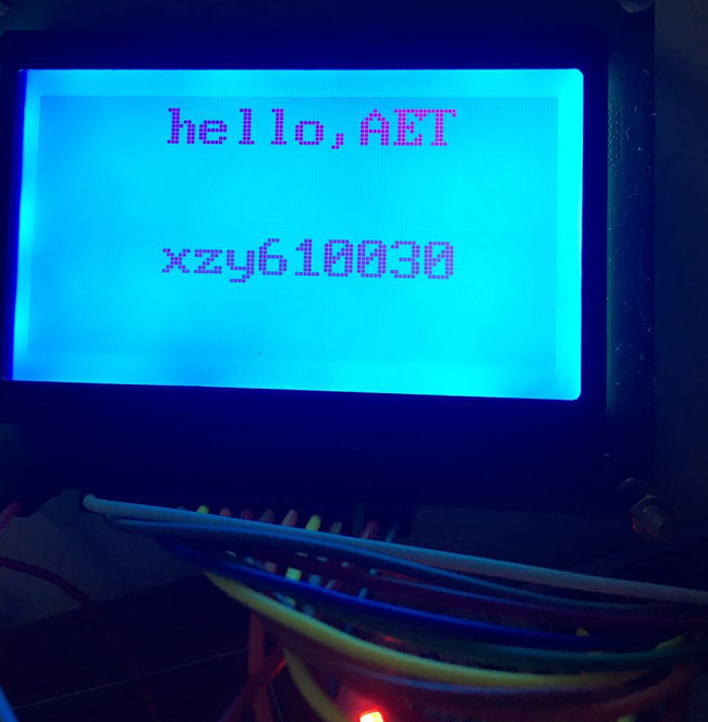
main函数主要就是调用了
unsigned char xiaozy1[] = "hello,AET";
unsigned char xiaozy2[] = "xzy610030";
lcd_12864_print(0, 2, xiaozy1);
lcd_12864_print(2, 2, xiaozy2);
值得说一下的是,显示数据RAM 提供64x2 个字节的空间, 最多可以控制4 行16 字( 64 个字) 的中文字型显示,地址如下:

上图:


调了一天,主要是初始化的时候没弄完,另外,在怀疑lcd坏了的时候,直接用FPGA驱动了一下,发现是好的,于是只是检查代码,发现了问题,而且之前怀疑了各种延迟,在后续看了,delay都是可以不用的,从上面的代码中也可以看到后面我把延迟都注释掉了。结果正常。
至今已经对stm32的开发有了初步的了解,继续~~~~另外,真的不得不赞一下,图片粘贴的功能啊,太棒了。
