Vivado基础学习之二:逻辑开发具体流程
1赞任务:利用Vivado创建工程,以分频为例。
目的:了解Vivado在逻辑编程的流程,熟悉软件的操作。
步骤:
双击Vivado2016.3,出现如下界面
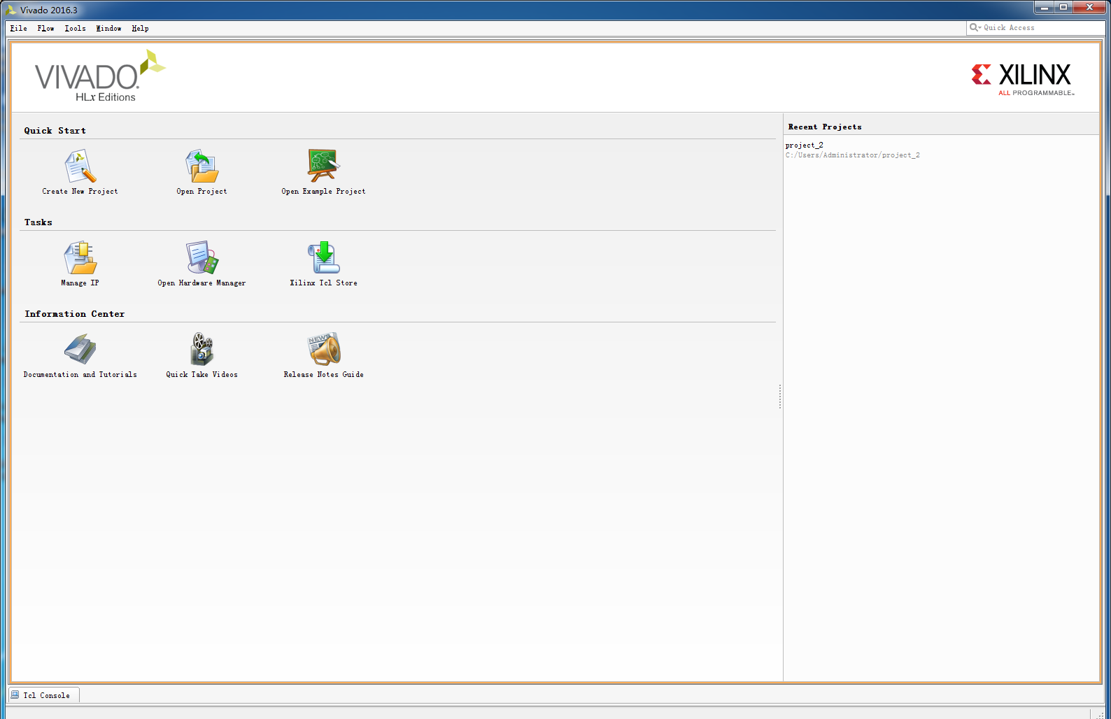
其中,Quick Start中有创建新工程,打开已有工程,打开示例工程。在界面的最右边可以看到最近打开的工程,最下方是Tcl控制台,即可以用Tcl命令操作。在这里我们直接选择新建工程。
2.根据新建工程导航窗口
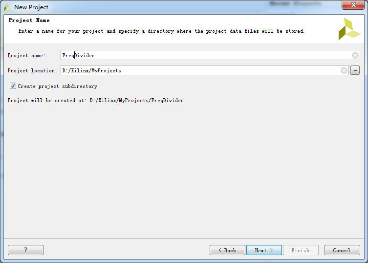
(1)填写工程名和工程目录,注不能用中文以及空格之内的特殊符号
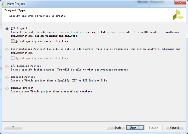
(2)选择工程类型,工程类型都有简介,有RTL、综合后工程、I/O分配工程、导入工程、示例工程,根据需要选择对应的类型。此处选择RTL工程。在选RTL工程时,如果勾选了Do not specify sources at this time,下一步就直接跳到器件选择,即(4);否则下一步就进入(3)界面。
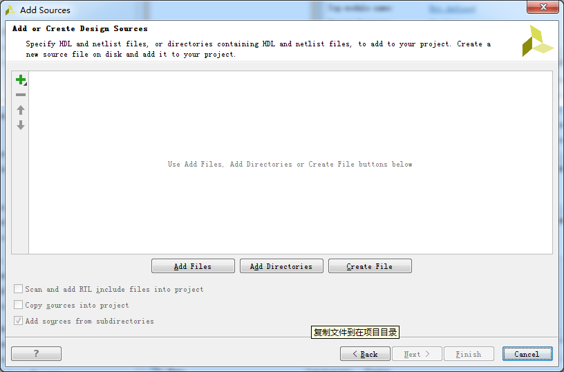
(3)为工程添加HDL源文件,这里也可以选择Create File


添加IP,没有就下一步

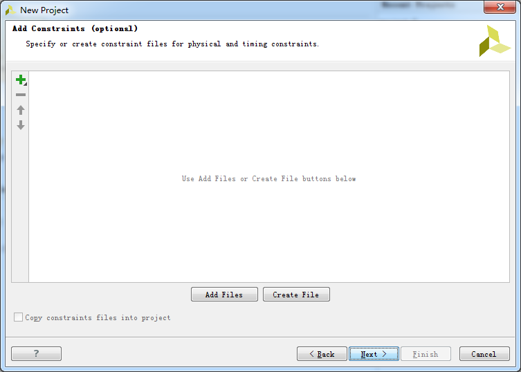
添加时序约束文件,没有就下一步。
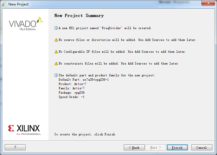
(4)选择器件(Parts)或电路板(Boards)。Vivado只支持7系芯片,但需要注意的是,目前最新版本是2016.3,对于最新出来的Spartan 7和部分其他系列7系芯片此处不一定能找得到。只能等待后续软件的更新。

(5)选好器件后,即可完成工程的新建。
3.完成后的界面。Flow Navigator:工程管理(project Manager),ip核(ip Integrator)、仿真(Simulation)、综合(Synthesis)、实现(Implementation)、下载与调试(program and debug)。在右边可以看到具体的工程管理(project Manager),包括了工程的组织结构,工程总结报告等诸多信息。

4.新建源文件:点击Project Manager下的Add Sources或者选中Sources下的Design Sources右击后选add sources。新建源文件的类型有时序约束、设计文件HDL、仿真文件、DSP文件、存在的块设计文件和IP。此处选择设计文件,即新建verilog文件。
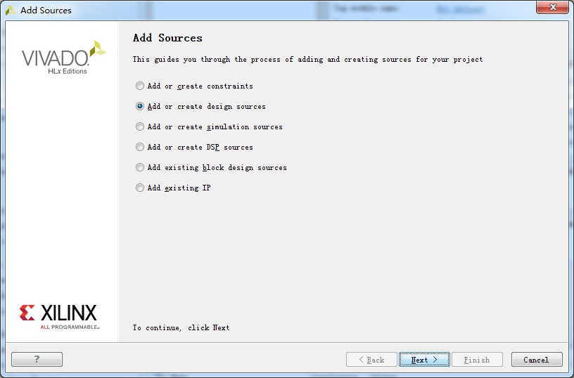
下一步之后又出现步骤2中可以出现的界面,此处和之前所述一样,有文件就添加,没有就新建,新建可以选择语言类型,填写文件名。
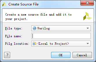

5.编写原文件程序。新建好的源文件就已经包含了头,模块名。在其中添加端口和自己逻辑就可以了

分频器的代码如下:
`timescale 1ns / 1ps
//////////////////////////////////////////////////////////////////////////////////
// Company:
// Engineer:
//
// Create Date: 2016/12/01 10:39:57
// Design Name:
// Module Name: FreDivider
// Project Name:
// Target Devices:
// Tool Versions:
// Description:
//
// Dependencies:
//
// Revision:
// Revision 0.01 - File Created
// Additional Comments:
//
//////////////////////////////////////////////////////////////////////////////////
module FreDivider(
        //sys
         input           sys_clk,
         input           sys_rst_n,
         //
         output   reg    led

);

//---------counter-------------------------------------------------------------
reg[24:0]counter;
always @(posedge sys_clk)
begin
     if(!sys_rst_n)                   counter <= 25'd0;
     else if(counter == 25'd2499)     counter <= 25'd0;
     else                             counter <= counter + 1'b1;
end

//---------output--------------------------------------------------------------
always @(posedge sys_clk)
begin
    if(!sys_rst_n)                      led <= 1'b0;
    else if(counter == 25'd2499)        led <= ~led;
end

endmodule
保存之后就可以进行仿真,编译综合等后续过程了。
6.Run Synthesis:综合,然后打开进行IO引脚分配
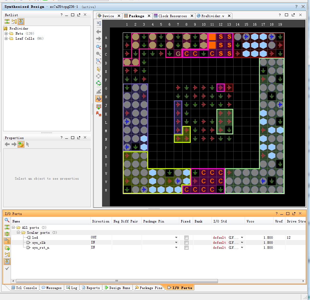
分配引脚后,保存由此生成的XDC文件

然后Tools-->Edit Device Properties-->Configration-->Configuration Bank Voltage Selection改为VCCO

此处可以添加需要的时序约束,具体的时序约束见后续博文。重新综合,再进行实现。
7.Run Implementation
生成Bit文件时会出现这样的警告:UCIO #1 3 out of 3 logical ports have no user assigned specific location constraint (LOC). This may cause I/O contention or incompatibility with the board power or connectivity affecting performance, signal integrity or in extreme cases cause damage to the device or the components to which it is connected. To correct this violation, specify all pin locations. This design will fail to generate a bitstream unless all logical ports have a user specified site LOC constraint defined. To allow bitstream creation with unspecified pin locations (not recommended), use this command: set_property SEVERITY {Warning} [get_drc_checks UCIO-1]. NOTE: When using the Vivado Runs infrastructure (e.g. launch_runs Tcl command), add this command to a .tcl file and add that file as a pre-hook for write_bitstream step for the implementation run. Problem ports: sys_clk, sys_rst_n, led.参照网上的说法,此警告是告诉用户需要设置set IOSTANDARD and PACKAGE_PIN,以便保护软件因为随机分配引脚导致的器件损坏。解决办法有两个:
(1)Add IOSTANDARD and PACKAGE_PIN constraints for all I/Os in the design
(2)If you do not care about those unconstrained I/Os, you use one of below solutions.for a GUI project flow, create a .tcl file and put below two commands in it. Specify this .tcl file in the "tcl.pre" option in "Bitstream Settings". Then you can re-run "Generate Bitstream" without re-running Implementation.
此处的疑问是引脚已经分配,为什么还会出现此警告。
根据提示将以下保存成tcl文件。
set_property SEVERITY {Warning} [get_drc_checks NSTD-1]
set_property SEVERITY {Warning} [get_drc_checks RTSTAT-1]
set_property SEVERITY {Warning} [get_drc_checks UCIO-1]
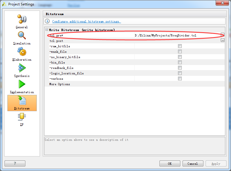
再重新生成即可。
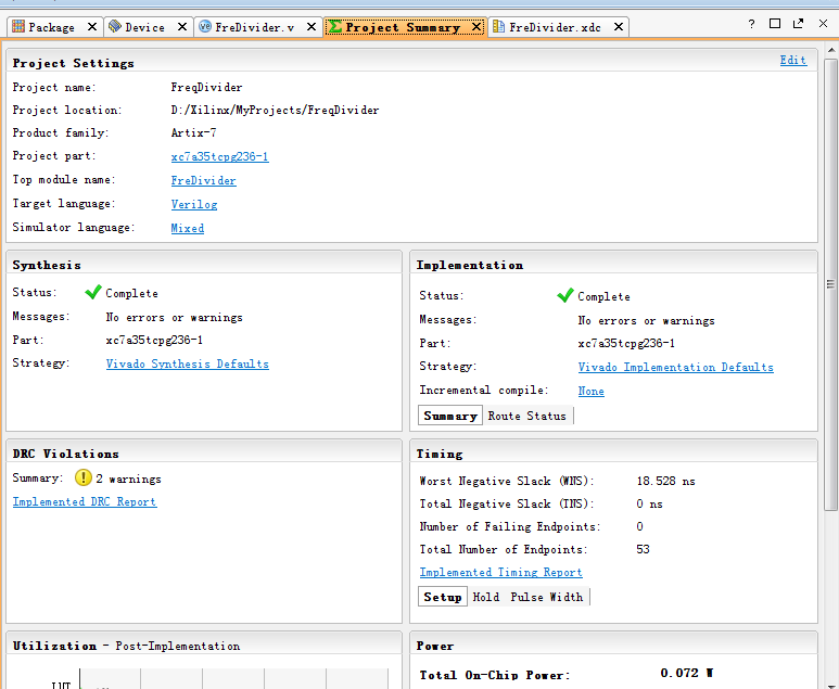
8.Program and Debug:生成了下载文件后就可以去查看链接的电路板了,这里因为暂时还没有硬件,后续步骤以后再加上。
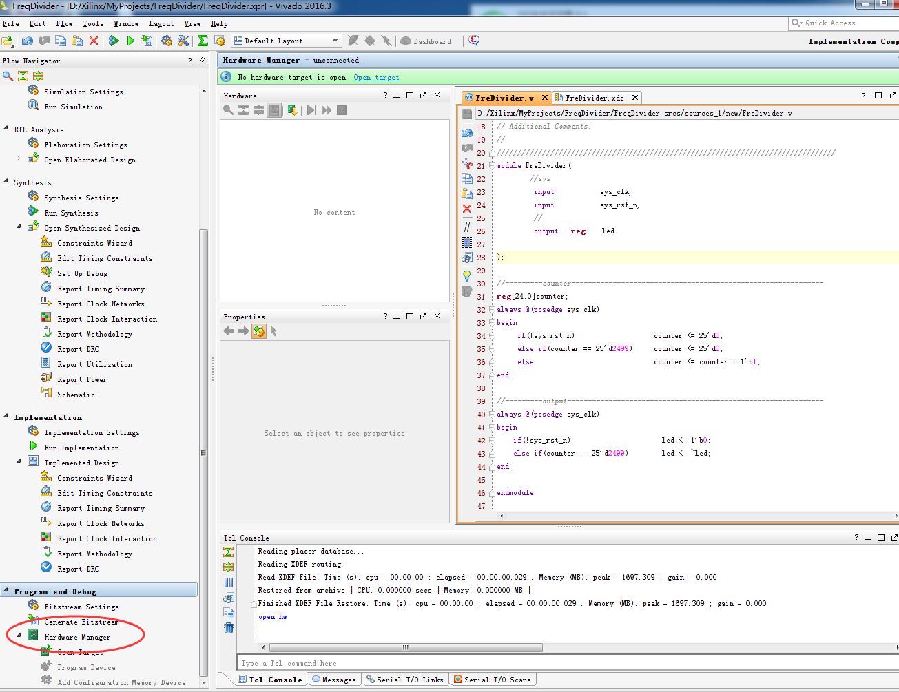
至此,利用Vivado进行逻辑编程的整个步骤就此结束。基本上与ISE差别不大。
